LOGO_CANBO_3-01

CNB-213 ELECTROMAGNETIC LOCKS


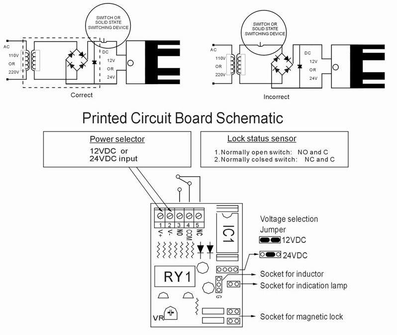
Magnetic Lock wiring instructions

A. 12VDC Input:
Required power 0.5Amp(Minimum).
Connect the positive(+)lead from a 12VDC power source to V +. 
Connect the ground(-)lead from a 12VDC power source to V -.
Check jumper for 12VDC operation.

B. 24VDC Input:
Require power 0.25 Amp(minimum).
Connect the positive(+)lead from a 24 VDC power source to V+.
Connect the ground (-)lead from a 24VDC power source to V-.
Check jumper for 24VDC operation.

C. Contacts:
Relay dry contacts are rated 1 Amp at 24VDC for safe operation, do not exceed this rating. If you require a normally open switch ,connect the wires from the system to COM and NO. If you require a normally closed switch,connect the wires from the system to COM and NC.

Important!
If power switch is not wired between DC source voltage and magnet ,it will take a longer time to de-energize the magnet simulating residual magnetism.(see below)

Please Read Before Attempting To Install Magnetic Lock

A. Handle the equipment with care, damaging the mating surfaces of the magnet or armature plate may reduce locking efficiency.

B. The magnet mounts rigidly to the door frame ,the armature plate mounts to the door with hardware.it provided that allows it to pivot about its center to compensate for door wear and misalignment.

C. Template use must take place with door in its normally colsed position.

D. Before installing, please add thread locker to all screws Firmly tighten screws to avoid fastening loosen.

Typical Installation:
** Important: Fix the armature plate not too tightly, and make the rubber washer mor flexible, in order to make the armature plate autonatically adjust its proper position with the magnet.

STEP 1

  • FOLD TEMPLATE ALONG DOTTED LINE.
  • PLACE TEMPLATE AGAINST DOOR AND HEAD FRAME.
  • DRILL HOLES AS INDICATED ON TEMPLATE.

STEP 2

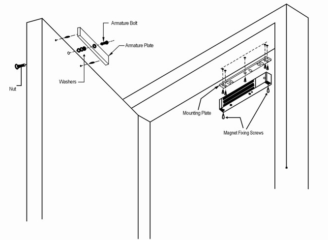
  • MOUNT THE ARMATURE PLATE TO DOOR USING 1 RUBBER WASHER SANDWICHED BETWEEN 2 STEEL WASHER(THE RUBBER WASHER AND 2 STEEL WASHER ARE INSTALLED ON THE THROUGH SEXNUT BETWEEN THE ARMATURE PLATE AND DOOR).

STEP 3

  • INSTALL THE MOUNTING PLATE
  • ADJUST THE MOUNTING PLATE SO THAT IT AND THE ARMATUTE PLATE FORM A RIGHT ANGLE.
  • USING THE MOUNTING PLATE AS A TEMPLATE DRILL THE WIRE HOLE.
  • DRILL AND INSTALL THE REMAINING MOUNTING SCREWS

STEP 4

  • INSTALL MAGNET TO MOUNTING PLATE WITH 2 M4(M6) SCREWS SUPPLIED.

STEP 5

  • INSTALL ELECTRICAL WIRING PER INSTRUCTION SHEET.

STEP 6

  • TEST ALL FUNCTIONS OF THIS MODEL (SEE WIRING INSTRUCTION)

Contact Now

Description

LOGO_CANBO_3-01

CNB-213 ELECTROMAGNETIC LOCKS

PRODUCT INFORMATION


Magnetic Lock wiring instructions

A. 12VDC Input:
Required power 0.5Amp(Minimum).
Connect the positive(+)lead from a 12VDC power source to V +. 
Connect the ground(-)lead from a 12VDC power source to V -.
Check jumper for 12VDC operation.

B. 24VDC Input:
Require power 0.25 Amp(minimum).
Connect the positive(+)lead from a 24 VDC power source to V+.
Connect the ground (-)lead from a 24VDC power source to V-.
Check jumper for 24VDC operation.

C. Contacts:
Relay dry contacts are rated 1 Amp at 24VDC for safe operation, do not exceed this rating. If you require a normally open switch ,connect the wires from the system to COM and NO. If you require a normally closed switch,connect the wires from the system to COM and NC.

Important!
If power switch is not wired between DC source voltage and magnet ,it will take a longer time to de-energize the magnet simulating residual magnetism.(see below)

PRINTED CIRCUIT BOARD SCHEMATIC

IMPORTANT

Please Read Before Attempting To Install Magnetic Lock

A. Handle the equipment with care, damaging the mating surfaces of the magnet or armature plate may reduce locking efficiency.

B. The magnet mounts rigidly to the door frame ,the armature plate mounts to the door with hardware.it provided that allows it to pivot about its center to compensate for door wear and misalignment.

C. Template use must take place with door in its normally colsed position.

D. Before installing, please add thread locker to all screws Firmly tighten screws to avoid fastening loosen.

Typical Installation:
** Important: Fix the armature plate not too tightly, and make the rubber washer mor flexible, in order to make the armature plate autonatically adjust its proper position with the magnet.

MOUNTING INSTRUCTION

STEP 1

  • FOLD TEMPLATE ALONG DOTTED LINE.
  • PLACE TEMPLATE AGAINST DOOR AND HEAD FRAME.
  • DRILL HOLES AS INDICATED ON TEMPLATE.

STEP 2

  • MOUNT THE ARMATURE PLATE TO DOOR USING 1 RUBBER WASHER SANDWICHED BETWEEN 2 STEEL WASHER(THE RUBBER WASHER AND 2 STEEL WASHER ARE INSTALLED ON THE THROUGH SEXNUT BETWEEN THE ARMATURE PLATE AND DOOR).

STEP 3

  • INSTALL THE MOUNTING PLATE
  • ADJUST THE MOUNTING PLATE SO THAT IT AND THE ARMATUTE PLATE FORM A RIGHT ANGLE.
  • USING THE MOUNTING PLATE AS A TEMPLATE DRILL THE WIRE HOLE.
  • DRILL AND INSTALL THE REMAINING MOUNTING SCREWS

STEP 4

  • INSTALL MAGNET TO MOUNTING PLATE WITH 2 M4(M6) SCREWS SUPPLIED.

STEP 5

  • INSTALL ELECTRICAL WIRING PER INSTRUCTION SHEET.

STEP 6

  • TEST ALL FUNCTIONS OF THIS MODEL (SEE WIRING INSTRUCTION)